WireGuard Article Series (4): WireGuard Quick Start
This article was last updated on: February 7, 2024 pm
Synopsis of the series:
- WireGuard article series (1): What is a VPN?
- WireGuard Part 2: Introduction to WireGuard - Fast, Modern, Secure VPN Tunnels
- WireGuard Part 3: WireGuard Installation
Get started quickly
You first want to make sure it’s right Conceptual overview There is a good grasp, then Install WireGuard。 After that, keep reading here.
Configuration in action
The individual configurations are as follows:

Command line interface
You can add a new interface through which the interface should automatically handle module loading:ip-link(8)
1 | |
IP addresses and peers can pass throughifconfig(8)orip-address(8)assignment
1 | |
Or, if you have only two peers in total, you can:
1 | |
The interface can be used with the included wg(8) The utility configures the key and the peer endpoint:
1 | |
or
1 | |
Finally, it can be used ifconfig(8) or ip-link(8) Active Interface:
1 | |
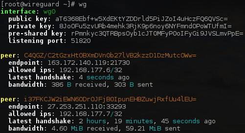
And alsowg show and wg showconfcommand to view the current configuration. without parameters wg invoke wg show The default is to make calls to all WireGuard interfaces.
wg(8) and ip(8)Many routine start-up and removal actions can be done through the included ones wg-quick(8)tool Automate it:

Key generation
WireGuard requires a base64-encoded public and private key. These can be used wg(8) Utility generation:
1 | |
This creates a new private key on stdout privatekeyof the content.
You can then derive the public key from the private key:
1 | |
This will be read from stdinprivatekeyand the corresponding public keypublickeyWrite stdout.
Of course, you can do it all at once:
1 | |
NAT and firewall traversal persistence
By default, WireGuard tries to be as silent as possible when not in use; This is not a talkative agreement. In most cases, it transmits data only when the peer wants to send the packet. When the system does not ask it to send a packet, it stops sending the packet until it is requested again. In most configurations, this works well. However, when a peer is behind a NAT or firewall, it may want to be able to receive incoming packets, even if it does not send any packets. Because NAT and stateful firewalls track “connections,” if a peer behind NAT or firewall wants to receive incoming packets, he must keep the NAT/firewall mapping valid by periodically sending keep-alive packets. This is calledPersistent keepalives。 When this option is enabled, keep-alive packets are sent to the server endpoint every few seconds. A reasonable interval of 25 seconds for various firewalls. Setting it to 0 turns off the feature, which is the default setting because most users don’t need it and makes WireGuard slightly more talkative. You can change the field PersistentKeepalive = Add a peer to the configuration file or set it on the command line persistent-keepaliveto specify this feature. If you do not need this feature, do not enable it. However, if you are behind a NAT or firewall and you want to receive incoming connections after network traffic has been silent for a long time, this option will leave Connection open in the NAT eye.
Configuration details
WireGuard uses the INI syntax as its configuration file format. The configuration file can be placed under any path, but must be referenced by an absolute path. The default path is /etc/wireguard/wg0.conf。
The configuration file must be named in ${WireGuard 接口的名称 }.conf。 Typically, the WireGuard interface name ends with wg for the prefix, and from 0 Start numbering, but you can also use other names, as long as they conform to the regular expression ^[a-zA-Z0-9_=+.-]{1,15}$ That’s it.
You can choose to use wg command to configure the VPN manually, but is generally recommended wg-quick, which provides a more robust and user-friendly configuration experience to manage configurations through configuration files.
Here’s an example configuration file:
1 | |
✔️ Practical configuration:
PostUp and PostDown can be configured as described above:
PostUp = iptables -A FORWARD -i %i -j ACCEPT; iptables -A FORWARD -o %i -j ACCEPT; iptables -t nat -A POSTROUTING -o eth0 -j MASQUERADEPostDown = iptables -D FORWARD -i %i -j ACCEPT; iptables -D FORWARD -o %i -j ACCEPT; iptables -t nat -D POSTROUTING -o eth0 -j MASQUERADE
Of course, the best practice for the current experience is to fool everything through Netmaker.
[Interface]
This section defines the on-premises VPN configuration. For example:
-
If the local node is a client, it only needs to route its own traffic, which only exposes one IP (as a client, you do not need to specify a port).
1
2
3
4[Interface]
# Name = phone.private
Address = 10.4.1.5/32
PrivateKey = <private key for phone.private> -
If the local node is a relay server, it needs to forward traffic to other peers and expose routes for the entire VPN subnet.
1
2
3
4
5
6[Interface]
# Name = public-server1.example-vpn.tld
Address = 10.4.1.1/24
ListenPort = 51820
PrivateKey = <private key for public-server1.example-vpn.tld>
DNS = 223.5.5.5
Address
Define which address range the local node should route.
- If it is a regular client, set it to a single IP of the node itself (specified with CIDR, for example, 10.4.1.3/32);
- If it is a relay server, set it to a routable subnet range.
For example:
- Regular clients, which route only their own traffic:
Address = 10.4.1.3/32 - A relay server that can forward traffic to other peers:
Address = 10.4.1.1/24(Note that it is.)/24, i.e. the entire subnet) - You can also specify multiple subnets or IPv6 subnets:
Address = 10.4.1.1/24,2001:DB8::/64
ListenPort
If the local node is a relay server, you need to specify the port to listen for incoming VPN connections through this parameter, and the default port number is Select 51820。 This option is not required for regular clients (client-side only, not server-side).
PrivateKey
The private key of the local node, which must be set by all nodes, including the relay server. Cannot be shared with other servers.
DNS
Advertise DNS servers to clients through DHCP. The client will use the DNS server specified here to handle DNS requests in the VPN subnet, but this option can also be overridden in the system. For example:
- If not configured, the system default DNS is used
- You can specify a single DNS:
DNS = 223.5.5.5 - You can also specify multiple DNS:
DNS = 223.5.5.5,223.6.6.6
MTU
Defines the connection to a peer MTU(Maximum Transmission Unit), which does not need to be set by default, is generally determined automatically by the system.
PreUp
The command that runs before the VPN interface is started. This option can be specified multiple times, sequentially.
For example:
- To add a route:
PreUp = ip rule add ipproto tcp dport 22 table 1234
PostUp
The command that runs after the VPN interface is started. This option can be specified multiple times, sequentially.
For example:
-
To read the configuration values from a file or from the output of a command:
1
PostUp = wg set %i private-key /etc/wireguard/wg0.key <(some command here) -
Add a line of log to the file:
1
PostUp = echo "$(date +%s) WireGuard Started" >> /var/log/wireguard.log -
Call WebHook:
1
PostUp = curl https://events.example.dev/wireguard/started/?key=abcdefg -
To add a route:
1
PostUp = ip rule add ipproto tcp dport 22 table 1234 -
Add an iptables rule to enable packet forwarding:
1
PostUp = iptables -A FORWARD -i %i -j ACCEPT; iptables -A FORWARD -o %i -j ACCEPT; iptables -t nat -A POSTROUTING -o eth0 -j MASQUERADE -
Force WireGuard to reresolve the IP address of the peer domain name:
1
PostUp = resolvectl domain %i "~."; resolvectl dns %i 10.4.1.1; resolvectl dnssec %i yes
PreDown
The command that was run before stopping the VPN interface. This option can be specified multiple times, sequentially.
For example:
-
Add a line of log to the file:
1
PreDown = echo "$(date +%s) WireGuard Going Down" >> /var/log/wireguard.log -
Call WebHook:
1
PreDown = curl https://events.example.dev/wireguard/stopping/?key=abcdefg
PostDown
Command that runs after stopping the VPN interface. This option can be specified multiple times, sequentially.
For example:
-
Add a line of log to the file:
1
PostDown = echo "$(date +%s) WireGuard Going Down" >> /var/log/wireguard.log -
Call WebHook:
1
PostDown = curl https://events.example.dev/wireguard/stopping/?key=abcdefg -
Delete the iptables rule and turn off packet forwarding:
1
PostDown = iptables -D FORWARD -i %i -j ACCEPT; iptables -D FORWARD -o %i -j ACCEPT; iptables -t nat -D POSTROUTING -o eth0 -j MASQUERADE
[Peer]
Defines VPN settings for peers that can route traffic for one or more addresses. A peer can be a relay server that forwards traffic to other peers, or a client that connects directly over the public or intranet.
The relay server must define all clients as peers, and no clients other than the relay server can define a node behind NAT as a peer because the route is unreachable. For those clients that route traffic only for themselves, simply treat the relay server as a peer, and other nodes that need direct access.
For example, in the following configuration,public-server1 As relay servers, other clients are either directly connected or behind NAT:
-
public-server1(Relay Server)[peer]:public-server2,home-server,laptop,phone -
public-server2(Direct Client)[peer]:public-server1 -
home-server(The client is behind NAT)[peer]:public-server1,public-server2 -
laptop(The client is behind NAT)[peer]:public-server1,public-server2 -
phone(The client is behind NAT)[peer]:public-server1,public-server2
Configuration example:
-
A peer is a reachable client that routes traffic only for itself
1
2
3
4
5[Peer]
# Name = public-server2.private
Endpoint = public-server2.private:51820
PublicKey = <public key for public-server2.private>
AllowedIPs = 10.4.1.2/32 -
A peer is a client that sits behind a NAT and routes traffic only for itself
1
2
3
4
5[Peer]
# Name = home-server.private
Endpoint = home-server.private:51820
PublicKey = <public key for home-server.private>
AllowedIPs = 10.4.1.3/32 -
A peer is a relay server that forwards traffic to other peers
1
2
3
4
5
6
7[Peer]
# Name = public-server1.example-vpn.tld
Endpoint = public-server1.example-vpn.tld:51820
PublicKey = <public key for public-server1.example-vpn.tld>
# 路由整个 VPN 子网的流量
AllowedIPs = 10.4.1.1/24
PersistentKeepalive = 25
Endpoint
Specifies the public network address of the remote peer node. This field is ignored if the peer is behind NAT or does not have a stable public network access address. Usually only needs to be specifiedRelay Servertarget EndpointOf course, nodes with stable public IP can also be specified. For example:
-
Specify by IP:
1
Endpoint = 123.123.123.123:51820 -
Specify by domain name:
1
Endpoint = public-server1.private:51820
AllowedIPs
The range of source addresses in VPN traffic sent by that peer. At the same time, this field will also be used as the IP address range bound by wg0 in the native routing table. If the peer is a regular client, set it to a single IP of the node itself; If the peer is a relay server, set it to a routable subnet range. Can be used , to specify multiple IP or subnet ranges. The field can also be specified multiple times.
When deciding how to route a packet, the system first selects the most specific route, and if it does not match, it chooses a broader route. For example, for a send to 10.4.1.3 packets, the system first looks for the address of 10.4.1.3/32 If the peer is no longer looking for the address for 10.4.1.1/24 of peers, and so on.
For example:
-
Peers are regular clients that route traffic only for themselves:
1
AllowedIPs = 10.4.1.3/32 -
A peer is a relay server that forwards traffic to other peers:
1
AllowedIPs = 10.4.1.1/24 -
Peers are relay servers that can forward all traffic, including Internet traffic and VPN traffic:
1
AllowedIPs = 0.0.0.0/0,::/0 -
A peer is a relay server that can route traffic for itself and other peers:
1
AllowedIPs = 10.4.1.3/32,10.4.1.4/32 -
A peer is a relay server that can route its own traffic and traffic to the intranet in which it resides:
1
AllowedIPs = 10.4.1.3/32,192.168.1.1/24
PublicKey
The public key of the peer, which must be set by all nodes, including relay servers. You can share the same public key with other peers.
The public key is available through commands wg pubkey < example.key > example.key.pub to generate, where example.key is the private key generated above.
For example:PublicKey = somePublicKeyAbcdAbcdAbcdAbcd=
PersistentKeepalive
If the connection is from a peer behind NAT to a peer, the peer behind NAT must periodically send an outbound ping packet to check connectivity, and if the IP changes, it is automatically updatedEndpoint。
For example:
- Local nodes can connect directly to peers: This field does not need to be specified because no connection check is required.
- The peer is behind NAT: this field does not need to be specified because it is the responsibility of the client (the initiator of the connection) to maintain the connection.
- The local node is behind NAT, and the peer is reachable to the public network: This field needs to be specified
PersistentKeepalive = 25, which means every day25A ping is sent once in seconds to check the connection.